IRF9630 P-Channel MOSFET: Specifications, Applications, and Equivalents
December 13, 2023 | by regularlearn.co.in
Explore the detailed specifications of the IRF9630 P-Channel MOSFET, featuring a voltage rating of 200V, current rating of -6.5A, and on-state resistance of 2.5 ohms. Learn about its applications and discover equivalent MOSFETs for versatile electronic designs.
IRF9630 P-Channel MOSFET Details
IRF9630 p-channel MOSFETData Sheet Overview:
Type: P-Channel MOSFET
Voltage Rating: 200V
Current Rating: -6.5A
Power Dissipation: 50W
Gate Threshold Voltage (VGS(th)): -2V to -4V
On-State Resistance (RDS(on)): 2.5 ohms (max)
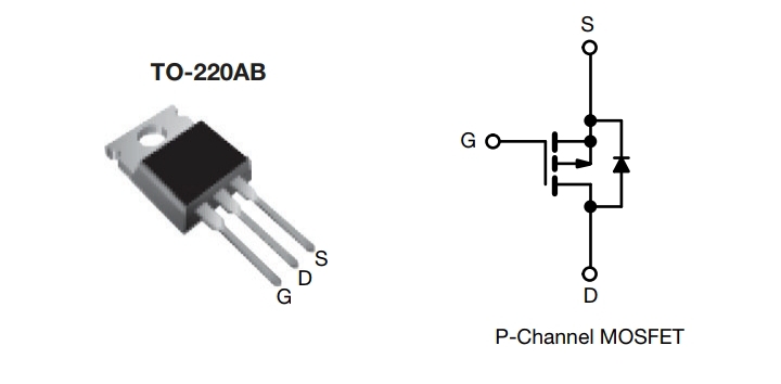
Package: TO-220AB
Equivalent MOSFETs:
IRF9630 P-Channel MOSFET Comparison Table
| Parameter | IRF9640 | IRF9630 | IRF9620 | IRF9610 | IRF9640N | IRFP9240 | IRF044 |
|---|---|---|---|---|---|---|---|
| Voltage Rating (V) | -200V | -200V | -200V | -200V | -200V | -200V | -60V |
| Current Rating (A) | -11A | -9A | -4.3A | -1.8A | -9A | -12A | -19A |
| Power Dissipation (W) | 125W | N/A | N/A | N/A | N/A | 150W | 140W |
| Gate Threshold Voltage (VGS(th)) | -2V to -4V | -2V to -4V | -2V to -4V | -2V to -4V | -2V to -4V | -2V to -4V | -2V to -4V |
| On-State Resistance (ohms) | 0.6 (max) | N/A | N/A | N/A | N/A | 0.3 (max) | 0.095 (max) |
| Package | TO-220AB | TO-220AB | TO-220AB | TO-220AB | TO-220AB | TO-247 | TO-220AB |
- IRF9640 Data Sheet
- IRF9630 Data Sheet
- IRF9620 Data Sheet
- IRF9610 Data Sheet
- IRF9640N Data Sheet
- IRF9640 Data Sheet
- IRF044 Data Sheet
Checking a MOSFET Using a Digital Multimeter
- Set Multimeter to Diode Test Mode:
- Turn on your multimeter and set it to the diode test mode. This mode is often represented by a diode symbol on the multimeter.
- Identify MOSFET Pins:
- Identify the three pins of the MOSFET: gate (G), drain (D), and source (S). Refer to the datasheet for your specific MOSFET to confirm pin configurations.
- Check Gate-Source Diode:
- Place the multimeter’s positive lead on the MOSFET’s gate (G) and the negative lead on the source (S). Note the reading.
- Reverse the leads (positive on source, negative on gate) and note the reading.
- If one direction shows a low resistance (near 0 ohms) and the other shows a high resistance (infinite or OL), the gate-source diode is likely intact.
- Check Drain-Source Diode:
- Place the positive lead on the MOSFET’s drain (D) and the negative lead on the source (S). Note the reading.
- Reverse the leads and note the reading.
- Similar to gate-source, if one direction shows low resistance and the other shows high resistance, the drain-source diode is likely intact.
- Check Gate-Drain Resistance:
- Measure the resistance between the gate (G) and drain (D) with the multimeter. It should read as an open circuit (infinite resistance).
- Check Gate-Source Voltage:
- Apply a small voltage (usually around 5V) between the gate (G) and source (S). This should be done with the MOSFET removed from the circuit. Monitor for any change in the drain-source resistance.