Explore MOSFET basics and learn how to check them with a digital multimeter
December 7, 2023 | by regularlearn.co.in

MOSFET Overview and how to check mosfet using digital multimeter
A MOSFET, or Metal-Oxide-Semiconductor Field-Effect Transistor, is a crucial component in electronic circuits for amplification and switching applications.
- Types of MOSFETs:
- N-Channel and P-Channel: MOSFETs come in two main types based on the majority charge carriers in the channel – N-Channel and P-Channel.
- Three Terminal Device:
- A MOSFET has three terminals: Gate (G), Source (S), and Drain (D).
- Operation Principle:
- The MOSFET operates on the principle of an electric field controlling the conductivity of a channel between the source and drain.
- Subtypes:
- Enhancement Mode: Requires a positive voltage at the gate to turn it on.
- Depletion Mode: Normally conducts and requires a negative voltage at the gate to turn it off.
- Applications:
- MOSFETs are used in amplifiers, digital circuits, voltage regulators, power supplies, and switching circuits.
- Advantages:
- High input impedance.
- Low power consumption.
- Fast switching speed.
- Compact size.
- MOSFET Symbols:
- In circuit diagrams, N-Channel and P-Channel MOSFETs are represented by different symbols.
- Classes:
- Bulk MOSFET: The traditional type with a bulk semiconductor material.
- SOI (Silicon on Insulator): Utilizes a thin layer of silicon on an insulating substrate.
- High-Side and Low-Side Switching:
- MOSFETs can be used for high-side or low-side switching depending on the application.
- Gate Drive Requirements:
- Proper gate drive voltage and current are crucial for MOSFET operation.

Checking a MOSFET Using a Digital Multimeter
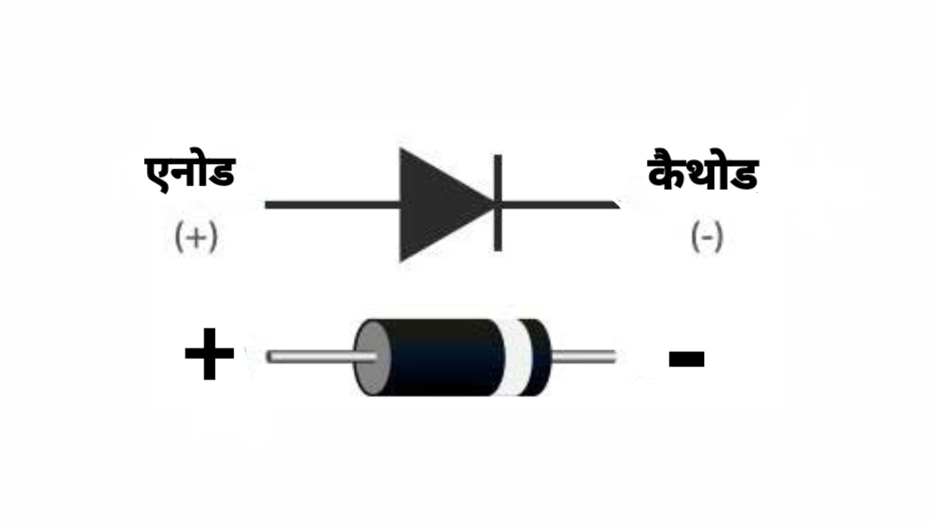
- Set Multimeter to Diode Test Mode:
- Turn on your multimeter and set it to the diode test mode. This mode is often represented by a diode symbol on the multimeter.
- Identify MOSFET Pins:
- Identify the three pins of the MOSFET: gate (G), drain (D), and source (S). Refer to the datasheet for your specific MOSFET to confirm pin configurations.
- Check Gate-Source Diode:
- Place the multimeter’s positive lead on the MOSFET’s gate (G) and the negative lead on the source (S). Note the reading.
- Reverse the leads (positive on source, negative on gate) and note the reading.
- If one direction shows a low resistance (near 0 ohms) and the other shows a high resistance (infinite or OL), the gate-source diode is likely intact.
- Check Drain-Source Diode:
- Place the positive lead on the MOSFET’s drain (D) and the negative lead on the source (S). Note the reading.
- Reverse the leads and note the reading.
- Similar to gate-source, if one direction shows low resistance and the other shows high resistance, the drain-source diode is likely intact.
- Check Gate-Drain Resistance:
- Measure the resistance between the gate (G) and drain (D) with the multimeter. It should read as an open circuit (infinite resistance).
- Check Gate-Source Voltage:
- Apply a small voltage (usually around 5V) between the gate (G) and source (S). This should be done with the MOSFET removed from the circuit. Monitor for any change in the drain-source resistance.
RELATED POSTS
View all